AB-129 - 5820-00-243-4127 - Antenna Base for AT-271A/PRC
AB-15/GR - 5985-00-221-5544 - Antenna Base (Antennevoet)Actually a part of the AT-271A/PRC portable antenna, that cannot be used without it.
AB-377 - 5985-17-039-9943 - Bag for Antenna Segments (Foudraal, antenne elementen)In the early manuals this older antenna base - dating back to the beginning of the fifties - was not mentioned. In later configuration lists however it shows up. See my ramblings on antenna configurations for a theory on what happened here.
AB-3600 - 5985-17-029-7726 - Antenna MastLight cotton duck bag to hold the two segments of the main vehicular antenna: AS-1730VRCMD and AT-1095.
AB-5242 - 5985-17-039-6946 - Fixture RF-3620 (Houder RF-3620)This is a mast, to be erected directly on the ground. It consists of:
(Not yet filled in)
AF-3620 - 5820-17-708-9895 - Control- and Loudspeaker Unit (Regel- en luidsprekereenheid)Never seen it, but it would seem to be a protective cover mounted over the RF-3620 antenna tuner/reducer.
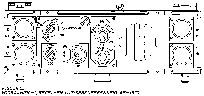
AM-3600 - 5820-17-708-9885 - RF Amplifier (Hoogfrequentversterker)This unit is used in vehicular configurations, allowing control over a single transceiver. Not only does it control the intercom and retransmitting, it also holds the main power switch for the PP-3620 mounted behind it. It has a built in loudspeaker, but no intercom capabilities. It has five controls and four connectors:
- 301/302 - male 8 pen connectors, power in/through on left and right hand sides. In a single stack one of these must be connected to the vehicle 24 Volt battery with cable CX-3600 (or CX-3607), leaving the other connector empty. In a double stack with an IC-3620 in the second stack, 301 (right) must be used for this connection, because 302 (left) will be hooked up to the IC-3620 with an UG-3608 in order to supply power to the second stack. If the second stack holds a second AF-3620, again power must be looped through with an UG-3608 but power in can be on either AF-3620.
- 303/304 - male 26 pen connectors, intercom on left and right hand sides. It takes the intercom cable CX-3611 or longer to connect the Control Boxes C-3621 in daisy chain fashion, eventually looping back unto the second intercom connector on the AF-3620. In a double stack, the same principle holds through, with the two inner 303/304 connectors hooked up with a UG-3626 - the second apparatus can be either a second AF-3620 or a IC-3620.
- 305 - main power switch for the stack the AF-3620 is part of, switching on the PP-3620. This switch also has an automatic fuse function. Stacks can be switched on and off individually.
- 306 - pilot light - lights up when stack is powered up. Has a turning lens to influence light intensity.
- 307 - on/off for built in loudspeaker.
- 308 - volume of built in loudspeaker.
- 309 - transmitter power (vermogen) switch chooses transmitting power in three stages - only functional if an AM-3600 HF amplifier is part of the RT-3600's controlled by this unit.
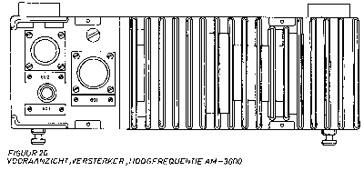
The amplifier to boost the RT-3600 to a 30 kilometre transceiver, slips in the back of the RT-3600. It has three connectors:
- 601 - male 26 pen connector, to be connected with a UG-3626 to a PP-3600 located either above or below. It's the systems internal within the stack.
- 602 - male 19 pen connector, for fixed cable on JB-3620. It carries the control signals for the antenna tuner.
- 603 - coaxial connector, for fixed cable on JB-3620. It carries the HF signals for the antenna tuner.
AN/GSA-6 - 5965-00-329-9085 - Chest Set (Borstschakelgarnituur)
A chest set is used in vehicles, as a switching assembly strapped unto the users chest that enables the user to choose different modes of communication, like intercom or radio. It's basically a switchbox. All chest sets in vehicular operation however also have a second very important function: they allow quick escape if the vehicle must be abandoned. Somewhere in the cabling there will be a quick release, breaking open when the user jumps out without having time for niceties as disengaging connectors.
The basic chest set in RT-3600/RT-3610 vehicular installations is the AN/GSA-6. Originally it stems from even older radio sets, using a different headset H-63/U - headphones combined with a boom microphone. Here, it is used with a T-30-V throat microphone and a H-4016 headphone.
The AN/GSA-6 has two fabric loops to tie in onto the users chest. One goes around the neck, the other high around the waist. It has three controls and three connectors:
Radio/Int - Radio or Interphone, governing whether the pressel switches (below) will activate transmission or Intercom.
Hold On - a momentary pressel switch. Microphone is active as long as this switch is kept down.
Lock On - a permanent pressel switch. Microphone is active until depressed again.
- 2 pen male JJ-055 style connector - for microphone lead from T-30-V.
- 3 pen male JJ-055 style connector - for headphone lead from H-4016.
8 pen receptacle (quick break) for cable to 10 pen audio connector.
AS-1730VRCMD - 5985-17-055-3230 - Antenna Segment (Lower)
AT-1095 - 5820-00-856-2728 - Antenna Segment (Upper)The lower segment of the vehicular antenna for the RT-3600. Not a Dutch development, both antenna segments were bought from the USA. However, the Dutch applied one small change: a small hole was drilled in the flange, in order to be able to secure it with a small string, against loosing.
Combined with the AT-1095 upper segment it forms a centre fed vertical dipole - the AS-1730VRCMD lower segment is coaxial, with the feed line in the centre.
AT-271A/PRC xxxx-xx-xxx-xxxx - Antenna, Portable Use, Long (Antenne, lang)The upper segment of the vehicular antenna for the RT-3600. Not a Dutch development, both antenna segments were bought from the USA.
This upper segment forms a vertical dipole combined with the lower segment, the AS-1730VRCMD.
AT-272A/PRC xxxx-xx-xxx-xxxx - Antenna, Portable Use, Short (Antenne, kort)The long antenna for man pack use - only with the RT-3600, as the RT-3610 has no option for the long antenna.
The Dutch used a well known and proven military antenna here, rather then designing their own model. Of course it will need the AB-129 in order to be mounted on the radio.
BB-3600 - xxxx-xx-xxx-xxxx - Nickel-Cadmium Battery (Nickel-Cadmium batterij)The short antenna for both the RT-3600 and RT-3610. No special Dutch development, this antenna is found on many radios of the era, in Nato countries.
BB-3610 - xxxx-xx-xxx-xxxx - Nickel Cadmium Battery (Nickel-Cadmium batterij)Still to do.
BB-4600 - xxxx-xx-xxx-xxxx - Nickel Cadmium Battery (Nickel-Cadmium batterij)Still to do.
BB-4610 - xxxx-xx-xxx-xxxx - Nickel Cadmium Battery (Nickel-Cadmium batterij)Only mentioned here because it can be charged with the PP-3600 Battery Charger. This battery cannot be used with the RT-3600 transceiver.
BG-3600 - xxxx-xx-xxx-xxxx - Harness, Man Pack for RT-3600 (Draagharnas)Only mentioned here because it can be charged with the PP-3610 Battery Charger. This battery cannot be used with the RT-3610 transceiver.
BG-3601 - 5820-17-039-3319 - Carrying Bag, Extra Parts (Draagtas)The original carrying harness for the RT-3600 transceiver is described in the manuals - and I even own one - but seems to have been replaced rather quickly by the BG-4600, which of course was designed for the RT-4600. As the original BG-3600 was a rather awkward design this would seem very understandable.
BG-3610 - 5820-17-711-0695 - Harness, Man Pack for RT-3610 (Draagharnas)This bag looks extraordinary like a Olive Drab shopping bag - with two handles. It's somewhat padded on the inside and has two flaps to close it. A RT-3600 fits in neatly for transport. However, it's not meant to actually use the radio in, transport and stowage of extra equipment only.
BG-4600 - 5820-17-052-4164 - Harness, Man Pack for RT-3600/RT-4600 (Draagharnas)Still to do.
BX-3600 - 6130-17-708-9881 - Battery Box (Batterijhouder)Strictly speaking this part should not be mentioned here - but the original BG-3600 carrying harness was rather badly designed and in daily use quickly got replaced by the BG-4600.
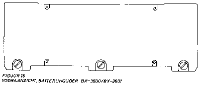
This battery box attaches to the back end of the RT-3600, thus making the unit fit for portable use.
It is for use with non rechargeable batteries.
BX-3601 - xxxx-xx-xxx-xxxx - Battery Box (Batterijhouder)
BX-3610 - 6130-17-708-9888 - Battery Box (Batterijhouder)This battery box attaches to the back end of the RT-3600, thus making the unit fit for portable use.
It is for use with rechargeble batteries. The charging unit is the PP-3600.
BX-3610/A - 6130-17-053-8962 - Junction Unit (Doorverbindingseenheid)This battery box attaches to the back end of the RT-3610, thus making the unit fit for portable use.
It is for use with non rechargeable batteries.
BX-3611 - xxxx-xx-xxx-xxxx - Battery Box (Batterijhouder)Junction Box, rebuilt from Battery Box BX-3610. It cannot hold batteries any longer, but has a permanent cable with a 26 pen female connector attached, that allows it to serve as a alternative for the combination of JB-3610 and UG-3626 when used in a vehicular stacked installation. It's the equivalent of the 751 connector of that JB-3610: the systems internal within the stack.
However, it differs greatly from the JB-3610 in design, as it lacks an equivalent to the 752 connector on the unit it can replace. That 752 carries HF signals and control signals for the antenna tuner RF-3610. So the only way a RT-3610 with this alternative Junction Unit can be connected to an antenna would be through the frontal antenna connector on the RT-3610. However, this is not a standard coaxial connector but a specialized one for the AT-272A/PRC antenna. The only possible use I see for this set-up would be in a jeep, with the RT-3610 on top of the stack, using it's own field antenna instead of the antenna tuner.
The BX-3610/A is not part of the earlier descriptions, so it seems likely it was decided at a later stage to modify battery boxes this way. One could wonder about the reason, was the portable use of the RT-3610 phased out, as it was a rather cumbersome transceiver compared to what technology could built only a sort period later?
C-3621 - 5820-17-708-9897 - Control Box Intercom (Schakelkast)This battery box attaches to the back end of the RT-3610, thus making the unit fit for portable use.
It is for use with rechargeable batteries. The charging unit is the PP-3610.
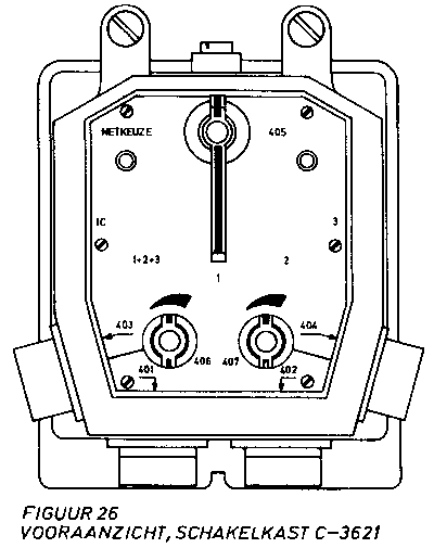
C-3625 - 5820-17-052-7442 - Control Box Intercom (Schakelkast)The Control Box for vehicular installations. It has it's own mounting: the MT-3621, for vehicular installations. It has three controls and four connectors:
- 401/402 - male 26 pen connectors, intercom on left and right hand sides. Connects to intercom cable CX-3611 or longer to daisy chain further Control Boxes, eventually looping back unto the intercom connectors on the transceiver stacks, connector 301 or 302 on the AF-3620 and connector 202 or 203 on the IC-3620.
- 403/404 - 10 pen audio connectors, type U-77/U for all available audio accessories.
- 405 - net selector (netkeuze) switch governing transceivers and intercom:
- IC - intercom only.
- 1+2+3 - listen to all transceivers and intercom, transmit over transceiver 1.
- 1 - listen and transmit over transceiver 1 plus intercom.
- 2 - listen and transmit over transceiver 2 plus intercom.
- 3 - listen and transmit over transceiver 3 plus intercom.
- 406/407 - volume controls for audio connectors 403/404.
This Control Box is mentioned in the literature, but personally I have never encountered one. Some descriptions seem to indicate this box was actually developed later, for the RT-4600/RT-4610 family, and retrofitted in RT-3600/RT-3610 installations.C-3686 - ????-??-???-???? - Remote Control Box (Afstandbedieningseenheid)
Part of the KL/GRA-3686 Remote Control Set; no NSN known, but marked 9556 304 054 on it's type plate. Actually developed for the later the RT-4600 radio family, but when available it pushed out the original Remote Control Set for the RT-3600, the AN/GRA-6.
It connects over field wire WD-1/TT to the C-3686A Local Control Box, over a maximum of 3 kilometres. It is labelled in English and has four controls, three connectors and three indicator lights:
- Call button - to ring Local Control Set.
- Function switch:
Off
Bat - Check batteries, Call/Battery Status should light up, otherwise replace batteries.
Tel - Telephone use to other set only.
TX1/RX1 - Transmit on radio 1, receive on radio 1.
TX1/RX1+2 - Transmit on radio 1, receive on radios 1 & 2.
TX2/RX1+2 - Transmit on radio 2, receive on radios 1 & 2.
TX2/RX2 - Transmit on radio 2, receive on radio 2.- Volume Calling Signal Switch - Volume of calling signal from other unit in 4 steps including silent (indicator light only).
- Volume Audio Signal Switch - Volume of audio signal from other unit in 7 steps including whisper mode. In whisper mode a hooked up loudspeaker will be silenced and microphone sensitivity will be boosted.
- Line - Two binding posts for field wire WD-1/TT to Local Control Box.
- Audio connector 5 pen - for H-6060 handset.
- Audio connector 10 pen - for LS-166/U loudspeaker.
- Status Light Call/Battery - lights up when Remote Control Box is calling or while testing batteries. Has a small mechanical shutter to cover it when light is not wanted.
- Status Light Radio 1 - flashes during incoming traffic on Radio 1 (actually, a squelch indicator). Has a small mechanical shutter to cover it when light is not wanted.
- Status Light Radio 2 - flashes during incoming traffic on Radio 2 (actually, a squelch indicator). Has a small mechanical shutter to cover it when light is not wanted.
The C-3686 needs 3 batteries, standard D cells, in order to operate.
C-3686A - ????-??-???-???? - Local Control Box (Lokale bedieningseenheid)
Part of the KL/GRA-3686 Remote Control Set; no NSN known, but marked 9556 304 053 on it's type plate. Actually developed for the later the RT-4600 radio family, but when available it pushed out the original Remote Control Set for the RT-3600, the AN/GRA-6.
It ties into the vehicular system with two fixed cables ending in 5 pen audio connectors, in order to control up to two transceivers and connects over field wire WD-1/TT to the C-3686 Remote Control Box, over a maximum of 3 kilometres. It is labelled in English and has four controls, two connectors, two fixed cables and one indicator light:
- Call button - to ring Remote Control Set.
- Function switch:
Off
Bat - Check batteries, Call/Battery Status should light up, otherwise replace batteries.
Tel - Telephone use to other set only.
TX1/RX1 - Transmit on radio 1, receive on radio 1.
TX1/RX1+2 - Transmit on radio 1, receive on radios 1 & 2.
TX2/RX1+2 - Transmit on radio 2, receive on radios 1 & 2.
TX2/RX2 - Transmit on radio 2, receive on radio 2.- Volume Calling Signal Switch - Volume of calling signal from other unit in 4 steps including silent (indicator light only).
- Radio family switch - Screw switch, position A for RT-3600., B for RT-4600.
- Line - Two binding posts for field wire WD-1/TT to Remote Control Box.
- Audio connector 5 pen - for H-6060 handset.
- Cable to Radio 1 - approx. 1.80 metres with 5 pen audio connector, goes straight to matching connector on transceiver number 1.
- Cable to Radio 2 - approx. 1.80 metres with 5 pen audio connector, goes straight to matching connector on transceiver number 2.
- Status Light Call/Battery - lights up when Remote Control Box is calling or while testing batteries. Has a small mechanical shutter to cover it when light is not wanted.
The C-3686A needs 3 batteries, standard D cells, in order to operate.
Antenna Cables (Antennekabels) for standard RT-3600
Complex cables assemblies, combining both H.F. Signals and Control Signals, connecting JB-3620 to RF-3620 in medium (8 kilometres) or long (30 kilometres) range RT-3600 vehicular installations.
CG-3601 - 5995-17-034-3956 - Antenna Cable, HF Signal & Control (Antennekabel)
Length: 1 meter.CG-3602 - 5995-17-034-3957 - Antenna Cable, HF Signal & Control (Antennekabel)Length: 2 meters.CG-3603 - 5995-17-034-3958 - Antenna Cable, HF Signal & Control (Antennekabel)Length: 3 meters.CG-3604 - 5995-17-034-3960 - Antenna Cable, HF Signal & Control (Antennekabel)Length: 4 meters.CG-3605 - 5995-17-034-3961 - Antenna Cable, HF Signal & Control (Antennekabel)Length: 5 meters.CG-3606 - 5995-17-048-3247 - Antenna Cable, HF Signal & Control (Antennekabel)Length: 6 meters.CG-3610 - 5995-17-039-0225 - Antenna Cable, HF Signal & Control (Antennekabel)Length: 10 meters. I am not sure if this cable was used in vehicular installations, but it is definitely part of the AB-3600 fixed antenna mast.
CG-3611 - xxxx-xx-xxx-xxxx - Antenna Cable (Antennekabel)
Antenna Extension Cables (Antenneverlengkabels) for standard RT-3600No further information at this moment - found it mentioned in literature without any further details. My guess would be this is a short extension cable.
Antenna Cables (Antennekabels) for standard RT-3610 and low power RT-3600Complex cables assemblies, combining both H.F. Signals and Control Signals, to be used as an extension in the connection between JB-3620 to RF-3620 in medium (8 kilometres) or long (30 kilometres) range RT-3600 vehicular installations.
CG-3613 - 5995-17-039-0223 - Antenna Extension Cable, HF Signal & Control (Antenneverlengkabel)
Length: 3 meters.CG-3615 - 5995-17-039-0224 - Antenna Extension Cable, HF Signal & Control (Antenneverlengkabel)Length: 5 meters.
Simple coaxial cables, connecting JB-3610 to RF-3610 in a RT-3610 low range (3 kilometres) vehicular installation. Also used in low power (3 kilometres) RT-3600 configurations, connecting the JB-3600 to the RF-3610.
CG-3621 - 5995-17-035-6051 - Antenna Cable, HF Signal (Antennekabel)
Coaxial cable. Length: 1 meter.CG-3622 - 5995-17-047-5796 - Antenna Cable, HF Signal (Antennekabel)Coaxial cable. Length: 2 meters.CG-3623 - 5995-17-035-6052 - Antenna Cable, HF Signal (Antennekabel)Coaxial cable. Length: 3 meters.CG-3624 - xxxx-xx-xxx-xxxx - Antenna Cable, HF Signal (Antennekabel)Coaxial cable. Length: 4 meters.CG-3625 - 5995-17-035-9702 - Antenna Cable, HF Signal (Antennekabel)Coaxial cable. Length: 5 meters.
Antenna Cables (Antennekabels) for standard RT-4600 - can be used also on RT-3600
Complex cables assembly, combining both H.F. Signals and Control Signals, connecting RT-3600 directly to RF-3620 in medium (8 kilometres) or long (30 kilometres) range RT-3600 vehicular installations. This cuts out the JB-3620.
CG-5826 - 5820-17-052-6466 - Antenna Cable, HF Signal & Control (Antennekabel)
Length: 1 meter.
CX-3600 - 5995-17-034-3959 - Power Cable (Voedingskabel)
CX-3606 - xxxx-xx-xxx-xxxx - Unknown CableThe main Power Supply cable. Documentation seems to indicate there was only one length available, though the actual length is not known to me.
CX-3607 - 5595-17-039-3331 - Power Distribution Cable (Voedingsverdeelkabel)The CX-3606 is mentioned in early manuals, as part of the man pack installations. Later manuals do not mention this cable any more. It would seem likely this cable was an audio cable, possibly a matching between the new 5 pen audio connector on the transceivers and the old 10 pen U-77 connectors on the audio accessories - or a splitter.
Intercom Cables (Boordkabels)An Y-shaped Power Cable, meant to connect to both a RT-3600 stack and a Battery Charger PP-3600 or PP-3610. These chargers - I've never even seen a picture yet - seem to have been part of the stacks.
CX-5244 - 5995-17-050-2325 - Cable, unknownThe RT-3600 Intercom System for vehicles used ready made cables in order to connect the control boxes to the transceiver stacks. These cables came in a number of lengths, complete with connectors on both sides that daisy chained the Control Boxes to each other and the stacks.
CX-3611 - 5995-17-034-3963 - Intercom Cable (Boordkabel)
Length: 1 meterCX-3612 - 5995-17-034-3964 - Intercom Cable (Boordkabel)Length: 2 metersCX-3613 - 5995-17-034-3965 - Intercom Cable (Boordkabel)Length: 3 metersCX-3614 - 5995-17-034-3966 - Intercom Cable (Boordkabel)Length: 4 metersCX-3615 - xxxx-xx-xxx-xxxx - Intercom Cable (Boordkabel)Length: 5 metersCX-3616 - xxxx-xx-xxx-xxxx - Intercom Cable (Boordkabel)Length: 6 meters
CY-3686 - 5820-17-055-8620 - Carrying Bag (Draagtas)Mentioned in "FM-3600/FM-4600 Nomenclatuur" as part of 5820-17-046-1952. No further details.
H-33/F/GY - 5965-12-157-8049 - Handset (Handtelemicrofoon)Carrying bag for KL/GRA-3686 Remote Control Set.
Rubberized bag with sling and inner divisions.
Actually, I will have to check if this really was a part of the RT-3600/RT-3610 family. I concluded so earlier, but I am starting to have my doubts, not being able to find the references I concluded this from. Same holds true for the H-33E/PT.
H-33E/PT - 5965-12-140-8091 - Handset (Handtelemicrofoon)
H-3600 - 5965-17-035-8553 - Handset (Handtelemicrofoon)Actually, I will have to check if this really was a part of the RT-3600/RT-3610 family. I concluded so earlier, but I am starting to have my doubts, not being able to find the references I concluded this from. Same holds true for the H-33/F/GY.
H-3610 - 5965-17-037-5776 - Handset (Handtelemicrofoon)Handset looking a lot like the H-33 series - but equiped with the 5 pen modern audio connector. As far as I know now, exclusively used with the man pack versions of the RT-3600 and RT-3610.
H-3620 - 5965-17-037-5777 - Headset (Hoofdtelemicrofoon)Handset looking a lot like the H-33 series - equiped with the 10 pen U-77/U audio connector. As far as I know now, exclusively used with vehicular configurations.
H-3625 - 5965-17-037-5803 - Headphones (Hoofdtelefoon)Used exclusively in man pack configurations, with the H-3630 chest set. It has two fixed cables:
- Microphone cable ending in 2 pen male JJ-055 style connector.
- Headphone cable ending in 3 pen male JJ-055 style connector.
There is some evidence that the combination of both H-3620 and it's accompanying chest set H-3630 are later developments.
H-3630 - 5965-17-037-5778 - Chest Set (Borstgarnituur)(Connector 5 pen new style)
Still to do.
H-4016 - 5965-17-037-7046 - Headphones (Hoofdtelefoon)Used exclusively in man pack configurations, with the H-3620 headphones. It has one switch, two connectors and one fixed cable:
- Pressel Switch - to activate transmitter.
- 2 pen male JJ-055 style connector - presumably for microphone lead from H-3620.
- 3 pen male JJ-055 style connector - presumably for headphone lead from H-3620.
- Fixed cable, approx. 1 metre, ending in 5 pen connector.
There is some evidence that the combination of both H-3630 and it's accompanying headset H-3620 are later developments.
H-5696 - 8415-17-052-9500 - Tank Helmet (Tankhelm)Heavy ear enveloping headphones for use in vehicles. it has one cable from the left hand ear shell, 45 centimetres, ending in a 3 pen male JJ-055 connector - fitting the AN/GSA-6 chest set it is exclusingly meant for.
Mine came with a MX - 6473 neatly packed in their individual cotton duck bags. The numbers were unreadable.
H-6060 - 5965-17-054-4040 - Handset (Handtelemicrofoon)U-77/U
Still to do.
H-63/U - ????-??-???-???? - Headset (Hoofdtelemicrofoon)Part of the KL/GRA-3686 Remote Control Set. Racal Acoustics, England. It has a rubber covered pressel switch and a shortish (1 metre) coiled cable ending in a 5 pen connector.
H-7188 - 5965-17-056-0977 - Handset (Handtelemicrofoon)Still to do.
IC-3620 - 5820-17-708-9891 - Control- and Intercom Unit (Regel- en intercomeenheid)Mentioned in later documentation. I have no idea as to for what purpose it was meant. I own a couple, they have no pressel switch and no normal connector, but come with two small copper alligator like clips.
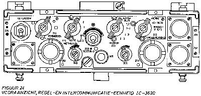
The major control unit in a vehicular installation - mandatory when there is a need for retransmitting. Not only does it control the intercom and retransmitting, it also holds the main power switch for the PP-3620 mounted behind it. No built in speaker. It has eight controls and five connectors:
- 201 - male 8 pen connector, power in. In a single stack this must be connected to the vehicle 24 Volt battery with cable CX-3600 (or CX-3607). In a double stack the IC-3620 must be on the left hand side, as power then is looped through from the 302 connector on the AF-3620 in the stack on the right side with an UG-3608. There can be no configuration with two IC-3620's, as power distribution would not be possible.
- 202/203 - male 26 pen connectors, intercom on left and right hand sides. It takes the intercom cable CX-3611 or longer to connect the Control Boxes C-3621 in daisy chain fashion, eventually looping back unto the second intercom connector on the IC-3620. In a double stack, the same principle holds through, with the two inner 202/304 connectors hooked up with a UG-3626 - the second apparatus must be either an AF-3620.
- 204/205 - 10 pen audio connectors, type U-77/U for all available audio accesories.
- 206 - main power switch for the stack the IC-3620 is part of, switching on the PP-3620. This switch also has an automatic fuse function. Stacks can be switched on and off individually.
- 207 - pilot light - lights up when stack is powered up. Has a turning lens to influence light intensity.
- 208/209 - volume controls for audio connectors 204/205.
- 210 - transmitter scope (zendbeperking) switch governing who can access the transmitter(s):
- Norm - transmitting is possible from both the IC-3620 and all connected Control Boxes C-3621.
- IC-3620 - transmitting only from IC-3620.
- Radiostilte (radio silence) - all transmitting blocked.
This switch does not refrain transmitting for audio accessories connected directly to the transceivers.
- 211 - net selector (netkeuze) switch governing transceivers and intercom:
- IC - intercom only.
- 1+2+3 - listen to all transceivers and intercom, transmit over transceiver 1.
- 1 - listen and transmit over transceiver 1 plus intercom.
- 2 - listen and transmit over transceiver 2 plus intercom.
- 3 - listen and transmit over transceiver 3 plus intercom.
- 212 - transmitter power (vermogen) switch chooses transmitting power in three stages - only functional if an AM-3600 HF amplifier is part of the RT-3600's controlled by this unit.
- 213 - duplex (bedrijf) switch controls retransmitting and duplex traffic:
- Norm - no duplex or retransmitting.
- Dupl 1, 2 - uses transceiver 1 for transmission and receiver 2 for receiving or vice-versa. Switch 211 governs this, with setting 1 or 2.
- 1-2 - retransmission using transceivers 1 and 2. When transceiver 1 receives, transceiver 2 retransmits the signal, when transceiver 2 receives the signal is retransmitted by transceiver 1.
- 1-3 - ditto, using transceiver 1 and 3.
- 2-3 - ditto, using transceiver 2 and 3.
- 214 - intercom reducer switch, reduces intercom signals while leaving receiver and field telephone signals at full strength.
JB-3600 - 5820-17-708-9882 - Junction
Unit (Doorverbindingskast)
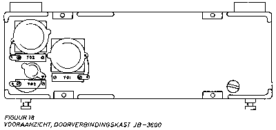
For vehicular use, the RT-3600 needs to be fitted with either this Junction Box or the AM-3600 amplifier. Both slip in the back of the RT-3600. It has three connectors:JB-3610 - 5820-17-708-9889 - Junction Unit (Doorverbindingskast)
- 701 - male 26 pen connector, to be connected with a UG-3626 to a PP-3600 located either above or below. It's the systems internal within the stack.
- 702 - male 19 pen connector, for fixed cable on JB-3620. It carries the control signals for the antenna tuner.
- 703 - coaxial connector, for fixed cable on JB-3620. It carries the HF signals for the antenna tuner.
If the RT-3600 is to be set up as a low power, 3 kilometre transceiver, 702 is not used and 703 will take a CG-3621 (or longer) cable to RF-3610. It carries HF signals to the antenna tuner.
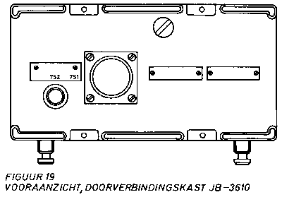
For vehicular use, the RT-3610 needs to be fitted with this Junction Box that replaces the battery box. It has two connectors:
- 751 - male 26 pen connector, to be connected with a UG-3626 to a PP-3600 located directly below. It's the systems internal within the stack.
- 752 - coaxial connector, for CG-3621 (or longer) cable to RF-3610. It carries HF signals to the antenna tuner.
As an alternative to the JB-3610 there is a BX-3610/A Junction Box, which is a rebuilt Battery Box. It has a different approach to hooking it up to the system, described under it's own heading.
JB-3620 - 5820-17-032-9109 - Junction Box (Doorverbindingsdoos)
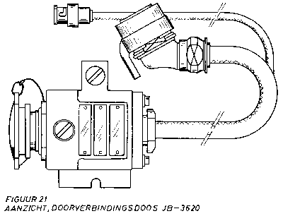
This Junction Box combines the separate radio- and control signals from a RT-3600 into the combined antenna cabling. It has one connector and two fixed cables:
- 901 - male ?? pen connector providing both H.F. and control signals to cable CG-3601 or longer running to the RF-3620 Antenna Mounting/Tuner.
- Coaxial cable taking H.F. signals from either AM-3600 R.F. Amplifier connector 603 or the JB-3600 Junction Unit connector 703, one of which will be mounted on the rear end of an RT-3600.
- 19 pen female cable taking control signals from either AM-3600 R.F. Amplifier connector 602 or the JB-3600 Junction Unit connector 702, one of which will be mounted on the rear end of an RT-3600.
The JB-3620 has it's own mounting plate: the MT-3622.
KL/GRA-3686 - xxxx-xx-xxx-xxxx - Remote Control Set (Afstandsbedieningsuitrusting)
Actually developed for the later the RT-4600 radio family, but when available it pushed out the original Remote Control Set for the RT-3600, the AN/GRA-6.LS-166/U - ????-??-???-???? - Loudspeaker (Luidspreker)
It is meant to enable remote use of up to two transceivers in a vehicular installation from a maximum distance of 3 kilometres, using WD-1/TT Field Cable. The different items are described under their own paragraphs:
- C-3686A Local Control Box (Lokale bedieningseenheid)
- C-3686 Remote Control Box (Afstandbedieningseenheid)
- H-6060 Handset (Handtelemicrofoon) 2x
- CY-3686 Carrying Bag (Draagtas)
- LS-166/U Loudspeaker (Luidspreker)
- IK-11-473 Instruction Card (Instructiekaart) 2x
Make a note that this is not a carbon mike, sot handsets cannot be interchanged!
LS-3621 - 5965-17-708-9898 - Amplified Loudspeaker (Luidsprekereenheid)Loudspeaker, non amplified, with old style 10 pen audio connector. Part of the KL/GRA-3686 Remote Control Set and packed in the CY-3686 Carrying Bag for this set, to be used with the C-3686 Remote Control Box. It has one control and one fixed cable:
- Switch - field or pack set use / vehicular use.
- Cable 1.80 metres ending in 10 pen audio connector.
It has a wing nut bracket on top for semi-permanent fixture.
The LS-166/U is actually older then the RT-3600/RT-3610 family, dating back to the beginning of the fifties and used with many different sets. It was made by many manufacturers worldwide, so NSN information should be treated with care.
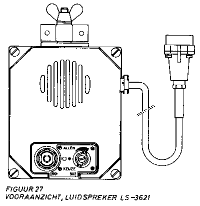
M-3600 - 5965-17-037-5804 - Microphone (Microfoon)An amplified loudspeaker, can be hooked up to any available old style (10 pen) audio-connector. It has one control and one fixed cable:
- 501 - switch governing the scope of signals heard:
- 502 - volume control.
- cable - to any available audio connector.
It can be fixed permanently with the wingnutted bracket on top but also has a magnet on the back to place it on metallic surfaces. This would not hold it in place while driving, so it will be meant for temporarily hooking up a speaker while stationary.
M-3610 - 5965-17-037-5805 - Microphone (Microfoon)(Connector 5 pen new style)
Still to do.
MS-117(A) - 5985-00-115-7149 - Antenna Element (Antennestaaf)(Connector U-77/U, old NATO style)
Still to do.
MS-118A/K - 5985-17-035-6046 - Antenna Element (Antennestaaf)The MS-117(A) is actually older then the RT-3600/RT-3610 family, dating back to the beginning of the fifties and used with many different sets. It was made by many manufacturers worldwide, so NSN information should be treated with care.
MT-3003 - xxxx-xx-xxx-xxxx - Mounting Double Radio Installation NEKAF (Montageplaat)The MS-118A/K is actually older then the RT-3600/RT-3610 family, dating back to the beginning of the fifties and used with many different sets. It was made by many manufacturers worldwide, so NSN information should be treated with care.
MT-3620 - 5975-17-708-9896 - Mounting for RT-3600 (Montageplaat)Still to do.
MT-3621 - 5975-17-033-3037 - Mounting for C-3621 (Montageplaat tbv de C-3621)The main mounting for the RT-3600 transceiver or stack of RT-3600 family apparatus. This mounting by itself cannot be mounted on any flat surface, it is meant to be placed upon a specialized mounting for the vehicle the installation will be part of. For instance, this MT-3620 can be mounted on the MT-3003 which is designed to fit in a NEKAF jeep.
MT-3622 - 5975-17-033-8240 - Mounting for JB-3620 (Montageplaat tbv de JB-3620)The C-3621 Control Box must be mounted on this MT-3621 mounting in a vehicular installation.
MT-5060 - xxxx-xx-xxx-xxxx - Mounting Double Radio Installation Landrover (Montageplaat)The JB-3620 Junction Box must be mounted on this MT-3622 mounting in a vehicular installation.
MT-5120 - 5975-17-049-7740 - Mounting for RT-3610 on RT-3600 (Montageplaat)Still to do.
MT-6183 - xxxx-xx-xxx-xxxx - Mounting, unknown (Montageplaat, onbekend)A small mounting designed to combine a RT-3610 with a RT-3600 stack. From a photo I have seen it would seem this mounting is meant to place the smaller RT-3610 neatly centred in the middle of the stack.
PP-3600 - 6130-17-034-9135 - Battery Charger for BB-3600/BB-4600 (Laadtoestel batterij tbv BB-3600/BB-4600)Mentioned in FM-3600/FM-4600 Nomenclatuur as part of 5820-17-046-1952. No idea what it actually is.
PP-3610 - 6130-17-034-9136 - Battery Charger for BB-3610/BB-4610 (Laadtoestel batterij tbv BB-3610/BB-4610)The battery charger for the BB-3600 rechargeable battery - also used with it's successor, the RT-4600 BB-4600.
This charger is designed to be part of a RT-3600 stack, it has the same mechanical fixtures as the other housings like the RT-3600 and the PP-3620. As I do not have much more then a badly copied drawing and the maintenance instructions for the actual batteries, I can only try to work out the controls. However, as far as I have been able to find out, the PP-3600 has two switches, one connector and four indicator lights:
- Function Switch:
0 - Off.
1 - Discharge. Start discharching cycle.
2 - Charge. Start charging cycle.
3 - Quick charge. Start quick charging cycle.
4 - Unknown- Start Pushbutton - starts the selected procedure
- Power Connector - same power connector as found on AF-3620 and IC-3620, uses cable CX-3607.
- Indicator Light Alarm (Alarm) - unknown.
- Yellow Indicator Light Discharging (Ontladen) - discharging in progress.
- Green Indicator Light Charging (Laden) - charging in progress.
- Blue Indicator Light Quick Charging (Snelladen) - quick charging in progress.
From my drawings I conclude there are also some fuses on the front panel.
PP-3620 - 6130-17-708-9892 - Power Supply (Voedingstoestel)The battery charger for the BB-3610 rechargeable battery - also used with it's successor, the RT-4610 BB-4610.
This charger is designed to be part of a RT-3600 stack, it has the same mechanical fixtures as the other housings like the RT-3600 and the PP-3620. As I do not have much more then a badly copied drawing and the maintenance instructions for the actual batteries, I can only try to work out the controls. However, as far as I have been able to find out, the PP-3610 has two switches, one connector and four indicator lights:
- Function Switch:
0 - Off.
1 - Discharge. Start discharching cycle.
2 - Charge. Start charging cycle.
3 - Quick charge. Start quick charging cycle.
4 - Unknown- Start Pushbutton - starts the selected procedure
- Power Connector - same power connector as found on AF-3620 and IC-3620, uses cable CX-3607.
- Indicator Light Alarm (Alarm) - unknown.
- Yellow Indicator Light Discharging (Ontladen) - discharging in progress.
- Green Indicator Light Charging (Laden) - charging in progress.
- Blue Indicator Light Quick Charging (Snelladen) - quick charging in progress.
From my drawings I conclude there are also some fuses on the front panel.
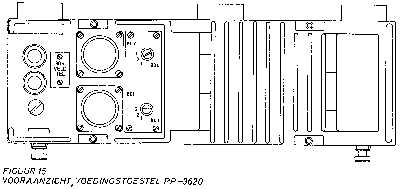
RF-3610 - 5920-17-708-9890 - Antenna Tuner / Mounting (reducing)The Power Supply, every stack must have one - inserted as the back unit of either the AM-3600 or the IC-3620. It has two switches and three connectors:
- 801 - male 26 pen connector, to be connected with a UG-3626 to a RT-3600 located directly below. It's the systems internal within the stack.
- 802 - male 26 pen connector, to be connected with a UG-3626 to a RT-3600 or a RT-3610 located directly above. It's the systems internal within the stack.
- 803 - Switch (screw, only to be set during setting up the installation) governing the number of the set directly below. It has three position: 1, 2 or 3. Normally 803 will be set to 1 as the first RT-3600 in an installation will be mounted underneath the Power Supply. In a second stack, 803 will normally be set at 3.
- 804 - Switch (screw, only to be set during setting up the installation) governing the number of the set directly above. It has three position: 1, 2 or 3. Normally 804 will be set to 2 as the second transceiver in an installation will be mounted above the Power Supply. In a second stack, 804 will normally not be used because of the limit of three transceivers in the system.
- 805 - (Bos Veld Telefoon) - pair of binding posts to include a field telephone in the intercom system.
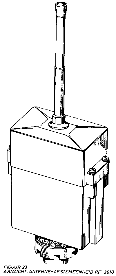
Basically this is the antenna mounting for a vehicular RT-3610 - but it can also be used with the RT-3600 for standard low power, a 3 kilometre set. If it is to be used as such, there is an internal switch to be set that kicks in a power reducer. In the documentation the RF-3610 is referred to as an antenna tuner, but the internal circuitry is very limited - and there are no control signals available from the transceiver. It seems to be a mounting primarily.
The antenna segments used with the RF-3610 are the well known MS-117(A) and MS-118A/K.The documentation mentions AB-5242 as a fixture for the RF-3610.
Strangely enough, the RF-3610 is not mentioned in recent manuals - but older antenna-bases like the AB-15/GR are...
It might be possible the RF-3610 was phased out later in the development of the system.
RF-3620 - 5985-17-035-4488 - Antenna Tuner / Mounting (Antenne-afstemeenheid)
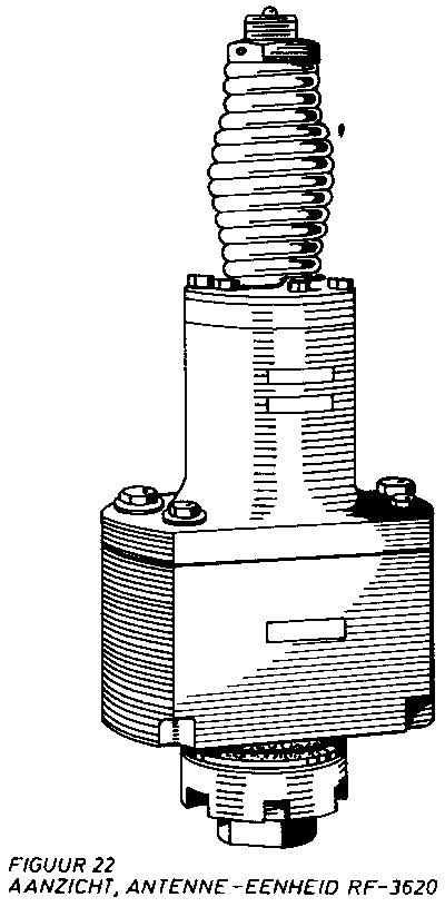
The basic antenna mounting/tuner for the RT-3600. Mechanically, it is a sturdy antenna base complete with a heavy duty spring in order to tie down antenna's while on the move. Within the base, there is the antenna tuner, in order to tune the antenna to the frequency used for transmitting.
In order to control that antenna tuner, the cabling is rather complex. The RF-3620 connects at the bottom to cable CG-3601 or longer, which carries not only the HF signals, but also the control signals.
There are a number of mechanical mounts for this unit on different vehicles, however, I have not looked into those yet.
Still to do.
RT-3600 - 5820-17-708-9880 - Transceiver (Zender/Ontvanger)
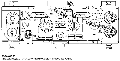
The most found transceiver in the family - capable of man pack use or vehicular use.
Still to do.
RT-3610 - 5820-17-708-9887 - Transceiver (Zender/Ontvanger)
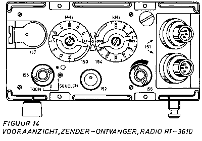
The smaller transceiver in the family - capable of man pack use or vehicular use, but primarily meant for man pack.
Still to do.
T-30-V - 5965-17-032-8786 - Microphone, Throat (Keelmicrofoon)
UG-3608 - 5935-17-034-8426 - Connector Assembly, 8 pen (8 polige connectorsamenstel)Throat microphone - carbon - that is meant to be used with the AN/GSA-6 chest set, for vehicular use. It has a special 2 pen female JJ-055 connector for this chest set, on a 30 centimetre cable.
UG-3618 - 5935-17-043-0300 - Connector Assembly, 8 pen (8 polige connectorsamenstel)A short dog bone that loops through the power connectors between two stacks. It's fixed length and somewhat flexible.
It fits connector 201 on the IC-3620 and connectors 301 and 302 on the AF-3620.
UG-3626 - 5935-17-034-8427 - Connector Assembly, 26 pen (26 polige connectorsamenstel)Mentioned in the literature, but no further information known at this point.
??? - 5820-00-908-6416 - Antenna Tie Down Rope AssemblyA short dog bone that loops through the system connectors, both within a stack and between two stacks. It's fixed length and somewhat flexible.
On the backside of a stack this dog bone will be found between connectors 801 and 802 of the PP-3620 and connector 601 of the AM-3600 or connector 701 of the JB-3600.
On the front the UG-3626 is used to loop through the intercom cabling between two stacks, connector 202 of the IC-3620 and connector 304 of the AF-3620.
??? - 5820-00-908-6416 - Antenna TipStill to do.
Still to do.
??? - 5820-00-437-2353 - Antenna Tip (Zoeten)
Still to do.
??? - 5120-17-029-7726 - Hammer (Hamer)
Still to do.
??? - 5340-17-039-8023 - Herring (Pen, grond)Part of AB-3600, 1x
Still to do.
??? - 5340-17-043-0383 - Belt (Riem)Part of AB-3600, 3x
Still to do.
??? - 5340-17-054-0501 - Mounting, Antenna (Draagstuk, antenne)Part of AB-3600, 2x
Still to do.
??? - 5975-17-039-3523 - Tie Down Plate (Tuiplaat)Part of AB-3600, 1x
Still to do.
??? - 5975-17-051-3944 - ?? (Trekontlasting)Part of AB-3600, 2x
Still to do.
??? - 5985-17-039-3520 - Ground Plate (Grondplaat)Part of AB-3600, 2x
Still to do.
??? - 5985-17-039-3521 - Mast Sections (Mastsecties)Part of AB-3600, 1x
Still to do.
??? - 5985-17-039-6947 - Holder Mast Section (Houder mastdelen)Part of AB-3600, 6x
Still to do.
??? - 5985-17-041-9581 - Herring (Pen, grond)Part of AB-3600, 2x
Still to do.
??? - 5985-99-637-9877 - Rope Assembly (Tuisamenstel)Part of AB-3600, 2x
Still to do.
??? - 5995-17-039-0225 - CG-3610 (Antennekabel)Part of AB-3600, 3x
Still to do.
??? - 8140-17-039-0278 - Chest (Kist)Part of AB-3600, 1x
Still to do.
Part of AB-3600, 1x